The blade angle can be adjusted within the blade holder to ensure the blade edge is parallel to the plane of oscillatory motion (parallel to the z-axis). By doing so, there will be minimal damage to the surface of the tissue resulting in a cleaner slice. Parallelism, also known as the z-axis deflection of the blade edge, is checked prior to slicing using the included "Opti-Cal" accessory.
The Opti-Cal provides non-contact measurement of the blade deviation from the z-axis whilst the blade is
vibrating..
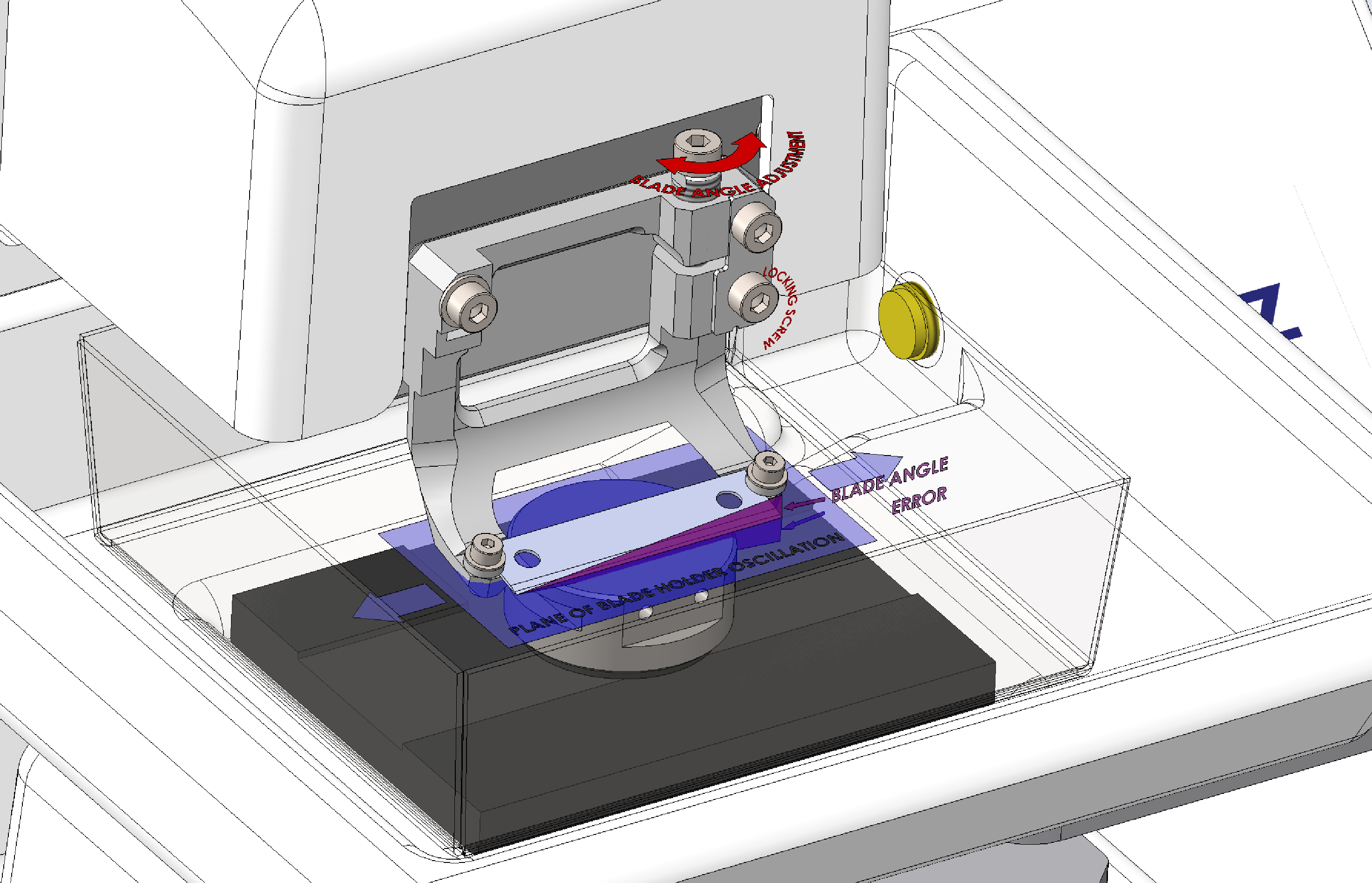 Blade Holder Features
The blade alignment calibration is performed using the following procedure and is accessed from the Start screen:
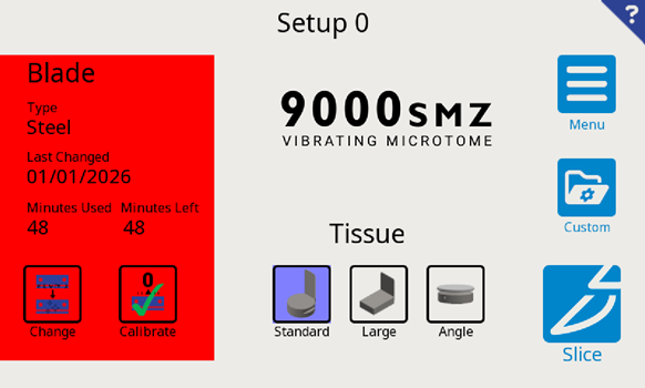
Ensure that the blade type (either stainless steel or ceramic) is selected on the Touchscreen. To change the blade type, select the blade button
![]() on the left-hand side of the screen.
Note: It is crucial that the correct blade type is selected prior to calibration, to ensure optimal blade alignment.
on the left-hand side of the screen.
Note: It is crucial that the correct blade type is selected prior to calibration, to ensure optimal blade alignment.
Toggle the blade type button
![]() between Stainless and Ceramic. Adjust the change time by pressing the button
between Stainless and Ceramic. Adjust the change time by pressing the button
![]() , this will bring up a keypad to set a value (in minutes). Press
, this will bring up a keypad to set a value (in minutes). Press
![]() when set.
Note: when the blade time exceeds the set time (in minutes), the ‘blade bubble’ in the start screen will turn red (see above).
when set.
Note: when the blade time exceeds the set time (in minutes), the ‘blade bubble’ in the start screen will turn red (see above).
11.2 Calibrating a Blade
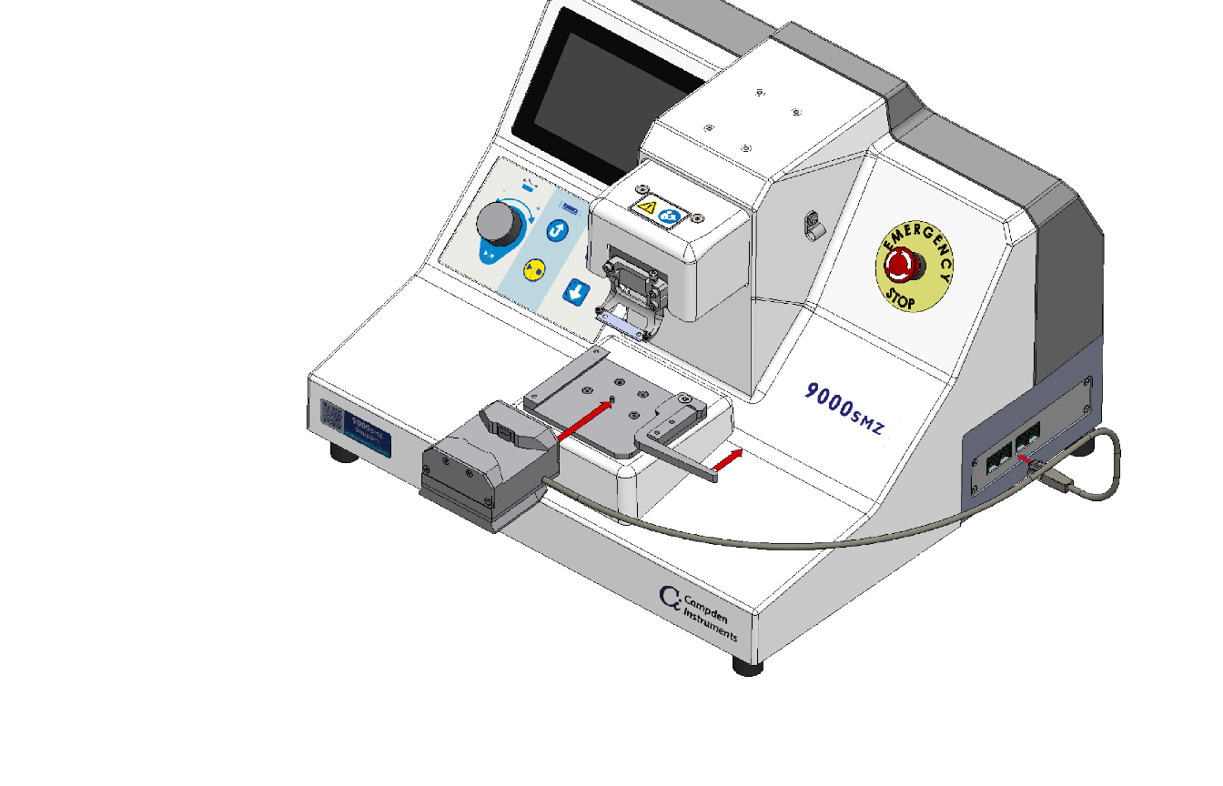
- To load the 9000SMZ Opti-Cal Calibration Unit, the spring-loaded lever should be pushed rearward. Slide the Opti-Cal with the dovetail arrangement until a positive stop is met. When it cannot be inserted further, releasing the lever holds the Opti-Cal in place..
- Plug the Opti-Call's electrical connector into any available port on the right side of the 9000SMZ; pushing the lever, allows for easy removal of the Opti-Cal unit. When the Opti-Cal is correctly mounted and connected, the 9000SMZ allows the calibration mode to be entered..
- Press the calibration buttonn
 on
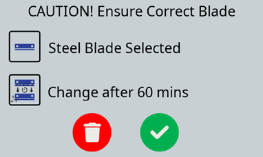
the touchscreen. A pop-up will appear checking the blade type installed, if
the incorrect blade type is installed press
on
the touchscreen. A pop-up will appear checking the blade type installed, if
the incorrect blade type is installed press
 and change the blade type via the blade button
 (Section 11.1).
Upon selection of the accept button
(Section 11.1).
Upon selection of the accept button
 the Blade Advance and the Stage/Opti-Cal combination will rise to the optimal blade alignment position..

Potential crush injury and risk of damage to equipment warning - Users to keep fingers clear of Opti-Cal. The Opti-Cal/Rising table combination will be driven automatically to the approximate blade measurement position. This may be stopped by pressing either the pause button or the Emergency Stop button  .
. - When the blade edge has been detected by the Opti-Cal sensor and its position has been optimized, the calibration screen will appear.
- Selecting the
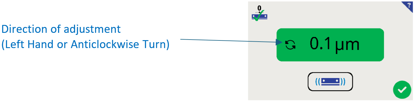
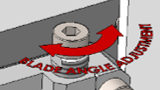
 calibrate button will initiate the blade to vibrate for a duration of approximately 3 seconds. The screen will then display the blade misalignment in microns. The screen will also display the direction to turn the Adjustment Screw on the Blade Holder.
The measurement bubble will indicate if the blade alignment falls within an acceptable reading..
• Readings above 1.0µm are displayed red.
• Readings between 0.5µm and 1.0µm are amber
• Readings below 0.5µm are green
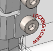
Adjust the blade alignment into the green zone for the very best slicing performance. - To align the blade, first use the 2.5mm hexagonal driver supplied in the
Toolkit to loosen the lower locking cap head screw on the blade holder. One
turn anticlockwise is sufficient.
- Using the same 2.5mm hexagonal driver, turn the Adjustment Screw, the vertical screw on the top right-hand corner of the blade holder by the smallest practical increment (less than 5°) in the direction indicated on the Touchscreen..
- Lightly re-tighten the lower locking screw..
- Select the calibratee
button on the Touchscreen.
- Repeat steps 8 - 11 until minimum blade alignment error has been achieved. This should be within a range of 0.1- 0.3µm.. Note: 0.0 is not physically possible to obtainn.
 |
Once the blade is within acceptable limits the lower locking screw may be tightened to a firm finger tightness. The locking screw should be tightened firmly with the tool provided. Do not over-tighten. Do not over-tighten. |
11.3 Blade Alignment Troubleshooting
Reduction of blade alignment error to an acceptable level may not be possible if the blade or the blade holder has been damaged. The replacement of the blade with a new blade should rectify this most of the time. Check cleanliness of blade, and the blade to Blade Holder interface (acetal washers).
With the blade alignment error minimized, the 9000SMZ is now ready to accept the Outer Bath. Press the
accept button
on the Touchscreen. The instrument will return to the Start screen and move to the load position. Remove the Opti-Cal when the Advance and Stage are fully retracted.